Posted by: Mauro 3 years, 9 months ago
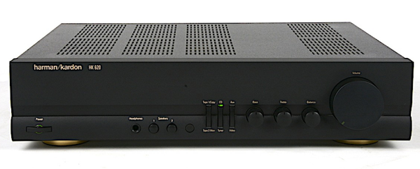
The Harman Kardon HK 620 is a stereo amplifier from the '90s. It is indeed a very nice amplifier... when it works.
My unit is affected by a weird issue: it stops sending the amplified signal to the speakers, while there is no sign of other malfunctions. The power LED and the input channel LEDs continue to work as expected, but there is absolutely no sound output on both left and right passive speaker.
There is no display on this device, so it's impossible to get a diagnostic message. However, it seems the amplifier enters some sort of "protection mode".
But hey, I'm not alone in this: the very same behavior is described in this instructable by ewilhelm.
The amazing fact is that the same "fix" applies in my case as well. Using a vacuum cleaner on the main board really brings back to life the HK 620.
Currently, the most convincing reason I can think of for this behavior is that using the vacuum cleaner successfully removes some residual static charge from the unit, which maybe causes it to go into protection mode. However, I still have no evidence for this, and I'd really like to spot the single component that needs to be replaced or simply discharged.
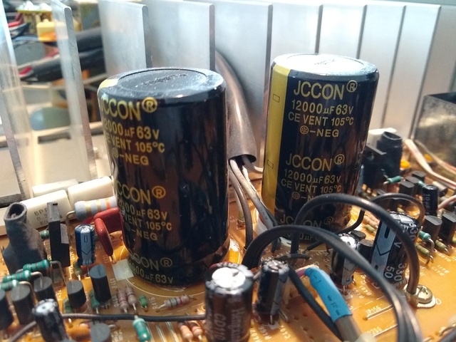
There are no clearly damaged components, and I even replaced the two big capacitors: when I did this, I initially thought I solved the problem, because the amplifier was working again... but then it stopped working a few days later, with the same symptoms. It is likely that taking off the main board and doing some soldering did a similar trick as vacuuming it... who knows?
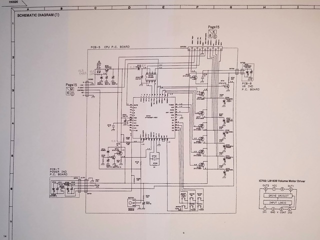
Online I found a scanned service/technical manual - I'll leave it here for reference: harman/kardon HK620 technical manual PDF
I'd really appreciate if anybody could drop a comment on how to further investigate/solve this problem, or simply offer some hints!
Update (2022 May):
I did some work on the amp, and now it's back, working again. Yet to see if the fix will be durable.
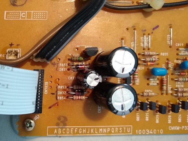
Basically, the majority of the electrolytic capacitors on the main board was desoldered and replaced with new components of equal or higher rating. Two 20V zener diodes were replaced as well (D831, D832) with higher wattage specs (1W) - one of them had darkened the PCB surface, I guess because of excessive and prolonged heating.
I found that many component pins and connections, even when the unit is disconnected from the 230V mains, keep a voltage way above or below ground for weeks. Actually voltages which are close to the regular ones when the unit is powered on.
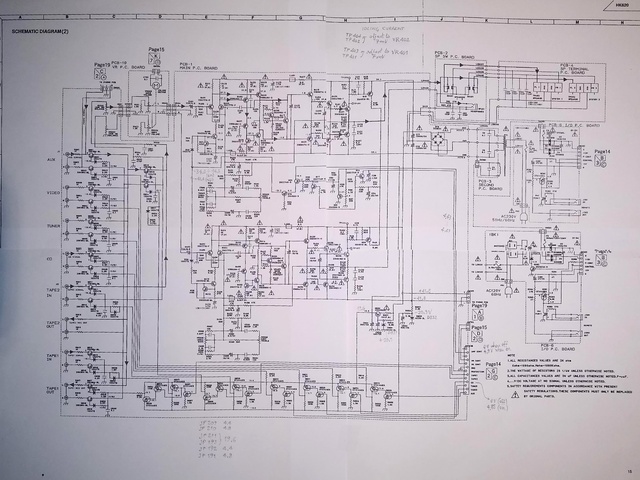
The schematic drawings in the service manual were very useful, especially the expected voltage readings "at rest" (unit turned on, with no input signal) in various points of the circuit.
For future reference, I took note, on the schematic drawing, of my actual voltage readings with no input signal applied.
Recent Posts
- harman/kardon HK 620 no speaker output
- Volvo XC60 cannot play (some) MP3 tracks
- Solarmax Inverters Data to MQTT
- Monitor your FRITZ!Box Internet bandwidth usage using lots of free software: Python, Redis, Raspbian, Mosquitto, Node-RED, InfluxDB, Grafana
- IoT garden irrigation for less than 30€
Archive
2021
2020
- October (1)
2019
- April (1)
2018
Categories
- arduino (4)
- IoT (6)
- open hardware (1)
- open source (4)
- networking (2)
- Cisco (1)
- audio (1)
Tags
- openenergymonitor grafana influxdb nodered mqtt mosquitto arduino esp8266 (1)
- grafana influxdb nodered mqtt mosquitto (1)
Authors
- Mauro (10)
Comments
There are currently no comments
New Comment