Posted by: Mauro 6 years, 8 months ago
Why would you ever want to know the IR protocol between an air conditioner and its remote control?
If you do this, it would then be easy to turn your A/C into an IP-controlled device!
If you know how to craft the signal, you could send it using a different controller: for example, an ESP8266 with MQTT and an IR led.
The first step is being able to read the signal in some form, then figure out how the bits are represented, and finally understand the structure of the messages (i.e. how operating mode, temperature, fan speed, etc. are encoded into the bit sequence).
Hardware setup:
- IR receiver module (a 3 pin component, I used a HS38B3)
- Arduino UNO
- breadboard and jumper wires
Software setup:
- Arduino IDE
- IRremote library
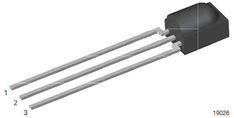 1 = OUT, 2 = GND, 3 = Vs
The connections are quite straightforward: pin 1 to an Arduino digital pin (e.g. 11), pin 2 to Arduino GND, pin 3 to Arduino 5V.
Install the IRremote library, then copy the IRrecvDumpV2 example in Arduino IDE, compile and flash. Start the serial monitor, grab your remote control and see if something happens when you press remote keys.
IRrecvDumpV2 tries to guess if your remote is among the known ones, and dumps the raw timings (marks and spaces) of the entire signal.
An A/C remote control is usually different from e.g. a TV remote: while the latter just encodes the key, and acts like a keyboard, the former encodes all the operating parameters and sends them all in every message. For example, when you set a new target temperature, the remote not only sends the temperature, but also the operating mode, fan speed, scheduled start and stop time, etc.
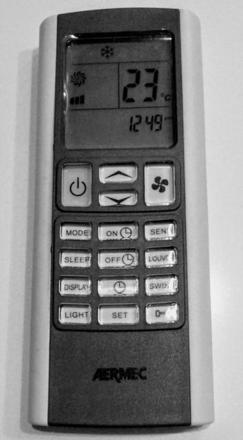
Aermec RC model C123

During the initial runs of IRrecvDumpV2, the first thing that needed attention was that the array of raw timings was overflowing: the signal was too long for the array default size (101).
The relevant configuraton is in IRremoteInt.h, where RAWBUF is defined: #define RAWBUF 255
With this new setting, I was finally able to get the timings of the whole signal. After spending some time trying to figure out recurring patterns in the signal, a few facts emerged:
- the base duration of both marks and spaces is 950 usec; all other durations are a multiple of this base duration
- the signal always starts with a mark of 3x base durations, followed by a space of 3x base durations
- the signal ends with a mark of 3x base durations
- in the middle of the signal, the pattern 3x mark 3x space occurs twice: this pattern is used as a separator, so that the overall signal structure is: [start pattern] + message1 + [separator] + message2 + [separator] + message3 + [end mark]
- message1 is equal to message2 and message3 (i.e. the message is repeated three times)
- within the message, no mark exceeds 2x base durations, and no space exceeds 2x base durations
The last observation indicates that bits are probably encoded using bi-phase coding. Every bit takes 2x base durations. "0" is mark+space (falling edge), "1" is space+mark (rising edge).
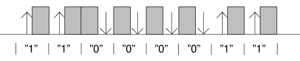
When "1" is followed by a "0", you get a 2x base duration mark. When "0" is followed by a "1", you get a 2x base duration space.
Every message is 80x base durations long. With bi-phase coding, this means encoding 40 bits, i.e. 5 bytes.
Unfortunately, none of the examples/protocols in IRremote library seemed to decode a bi-phase encoded signal, so I wrote my own decode function, following the useful guidance in ir_Template.cpp:
#define BITS          40  // The number of bits in the command

#define HDR_MARK    2850  // The length of the Header:Mark
#define HDR_SPACE1  3800  // The lenght of the Header:Space when first data bit = 1
#define HDR_SPACE0  2850  // The lenght of the Header:Space when first data bit = 0

#define HALF_BIT_US  950  // The length of a half bit

// match_mark and match_space rewritten to use a fixed tolerance,
// not a percentage of mark/space duration
#define USEC_TOLERANCE  250

// Due to sensor lag, when received, Marks tend to be 100us too long
int  match_mark (int measured_ticks,  int desired_us)
{
  bool passed = (((measured_ticks*USECPERTICK - MARK_EXCESS) >= (desired_us - USEC_TOLERANCE))
                && ((measured_ticks*USECPERTICK - MARK_EXCESS) <= (desired_us + USEC_TOLERANCE)));
  return passed;
}

// Due to sensor lag, when received, Spaces tend to be 100us too short
int  match_space (int measured_ticks,  int desired_us)
{
  bool passed = (((measured_ticks*USECPERTICK + MARK_EXCESS) >= (desired_us - USEC_TOLERANCE))
                && ((measured_ticks*USECPERTICK + MARK_EXCESS) <= (desired_us + USEC_TOLERANCE)));
  return passed;
}

#if DECODE_AERMEC
bool  IRrecv::decodeAermec (decode_results *results)
{
    // unsigned long  data   = 0;  // Somewhere to build our code
    unsigned short hbit[255];
    byte data[15];
    int offset = 1;  // Skip the Gap reading
    int hbits = 0;

    // Check we have the right amount of data
    // if (irparams.rawlen != 1 + 2 + (2 * BITS) + 1)  return false ;

    // Check initial Mark+Space match
    if (!match_mark(results->rawbuf[offset++], HDR_MARK ))  return false ;

    if (match_space(results->rawbuf[offset], HDR_SPACE1)) {
        hbits = 1;
        hbit[0] = 0; // 1st half bit = 0
    }
    else if (!match_space(results->rawbuf[offset], HDR_SPACE0)) return false;
    offset++;

    // Read the half bits in
    while (hbits < 255) {
        if (match_mark(results->rawbuf[offset], HALF_BIT_US)) {
            // data = (data << 1) | 1 ; // push 1
            hbit[hbits] = 1;
            hbits++;
        }
        else if (match_mark(results->rawbuf[offset], HALF_BIT_US*2)) {
            // data = (data << 2) | 3 ; // push 11
            hbit[hbits] = 1; hbit[hbits+1] = 1;
            hbits+=2;
        }
        else if (match_mark(results->rawbuf[offset], HALF_BIT_US*3)) {
            // data = (data << 3) | 7 ; // push 111
            hbit[hbits] = 1; hbit[hbits+1] = 1; hbit[hbits+2] = 1;
            hbits+=3;
        }
        else if (match_mark(results->rawbuf[offset], HALF_BIT_US*4)) {
            // data = (data << 4) | 15 ; // push 1111
            hbit[hbits] = 1; hbit[hbits+1] = 1; hbit[hbits+2] = 1; hbit[hbits+3] = 1;
            hbits+=4;
        }
        else return false;
        offset++;

        if (hbits < 255) {
          if (match_space(results->rawbuf[offset], HALF_BIT_US)) {
            // data = (data << 1) | 0 ; // push 0
            hbit[hbits] = 0;
            hbits++;
          }
          else if (match_space(results->rawbuf[offset], HALF_BIT_US*2)) {
            // data = (data << 2) | 0 ; // push 00
            hbit[hbits] = 0; hbit[hbits+1] = 0;
            hbits+=2;
          }
          else if (match_space(results->rawbuf[offset], HALF_BIT_US*3)) {
            // data = (data << 3) | 0 ; // push 000
            hbit[hbits] = 0; hbit[hbits+1] = 0; hbit[hbits+2] = 0;
            hbits+=3;
          }
          else if (match_space(results->rawbuf[offset], HALF_BIT_US*4)) {
            // data = (data << 4) | 0 ; // push 0000
            hbit[hbits] = 0; hbit[hbits+1] = 0; hbit[hbits+2] = 0; hbit[hbits+3] = 0;
            hbits+=4;
          }
          else return false;
          offset++;
        }
    }
    DBG_PRINTLN("Half-bits sequence:");
    for (int i = 0; i<255; i++) DBG_PRINT(hbit[i]);
    DBG_PRINTLN("");

    // check for separator mark and space (3 half-bits mark, 3 half-bits space)
    if (!hbit[80] || !hbit[81] || !hbit[82]) return false;
    if (hbit[83] || hbit[84] || hbit[85]) return false;

    if (!hbit[166] || !hbit[167] || !hbit[168]) return false;
    if (hbit[169] || hbit[170] || hbit[171]) return false;
        DBG_PRINTLN("111000 mid sep passed.");
    // check for end mark (3 half-bits)
    if (!hbit[252] || !hbit[253] || !hbit[254]) {
        DBG_PRINTLN("111 end mark failed.");
        return false;
    }

    int koff[] = {0, 86, 172};

    for (int k = 0; k<3; k++) {
      for (int b = 0; b<5; b++) {
        for (int i = 0; i<8; i++) {
            offset = koff[k] + ((b*8+i)*2);
            if ( !(hbit[offset]) && (hbit[offset+1]) )      // 0->1 transition is bit 1
                data[k*5+b] = (data[k*5+b] << 1) | 1 ;
            else if ( (hbit[offset]) && !(hbit[offset+1]) ) // 1->0 transition is bit 0
                data[k*5+b] = (data[k*5+b] << 1) | 0 ;
            else return false;                              // anything else aborts decoding
        }
      }
    }
    DBG_PRINTLN("Bit seq:");
    for (int i = 0; i<15; i++) {
        DBG_PRINT(data[i], HEX);
        DBG_PRINT(" ");
    }
    DBG_PRINTLN("");

    for (int b = 0; b<5; b++) {
        if ( (data[b] != data[b+5]) || (data[b] != data[b+10]) ) return false;
    }
    unsigned long val = 0;
    val += data[1];    val = val << 8;
    val += data[2]; val = val << 8;
    val += data[3]; val = val << 8;
    val += data[4];
    // Success
    results->bits        = BITS;
    results->address     = data[0];
    results->value       = val;
    results->decode_type = AERMEC;
    return true;
}
#endif
The decodeAermec function is far from being optimized and is not a beautiful piece of code, but it works.
To overcome the fact that the decoded value is a 32 bit integer (and 40 were needed), I put the first byte in the "address" property of the results structure.
With the correct decode function in place, it was time to play with the remote control, looking at how bits changed when operating on a given setting.
For example, the message for 24°C, fan auto, mode cool, no power-on timer and no power-off timer is 1C:12:00:00:06.
If you set "sleep" mode in addition, the message becomes: 1C:13:00:00:06.
If you take the temperature setting to 23°C (sleep mode still on): 1C:11:00:00:06.
Removing "sleep" mode, at 23°C, the reading becomes: 1C:10:00:00:06.
First nibble (bit 0 to 3): power on/off and operating mode
| 1xxx | power on/off |
| 0001 | mode: cool |
| 0010 | mode: heat |
| 0101 | mode: fan |
| 0100 | mode: dry (dehumidifier) |
| 0011 | mode: auto [triangle of arrows] |
| 0000 | off and timer set (?) |
Second nibble (bit 4 to 7): fan speed and "I feel"
| 00xx | fan speed 1 (low) |
| 01xx | fan speed 2 (med) |
| 10xx | fan speed 3 (high) |
| 11xx | fan speed AUTO |
| xx1x | "I feel" mode set |
| xxx0 | (not used, always 0) |
2nd byte: temperature and "sleep" mode
| hex | bin | use / description |
| 00 | 0000 000x | 15°C set temp |
| 20 | 0010 000x | 16°C set temp |
| 40 | 0100 000x | 17°C set temp |
| 60 | 0110 000x | 18°C set temp |
| 80 | 1000 000x | 19°C set temp |
| A0 | 1010 000x | 20°C set temp |
| C0 | 1100 000x | 21°C set temp |
| E0 | 1110 000x | 22°C set temp |
| 10 | 0001 000x | 23°C set temp |
| 12 | 0001 001x | 24°C set temp |
| 14 | 0001 010x | 25°C set temp |
| 16 | 0001 011x | 26°C set temp |
| 18 | 0001 100x | 27°C set temp |
| 1A | 0001 101x | 28°C set temp |
| 1C | 0001 110x | 29°C set temp |
| 1E | 0001 111x | 30°C set temp |
| xxxx xxx1 | "sleep" mode set |
3rd byte: power-on timer
Central unit has no clock: timers are countdowns starting from "now", measured in 10 minutes steps.
10' ahead is 0x01, 50' ahead is 0x05, but 1h ahead is 0x08 (a +3 increment instead of +1: this happens for every hour).
2h ahead is 0x10, 20h ahead is 0xA0, 23h50' ahead is 0xB5.
4th byte: power-off timer
See 3rd byte.
5th byte: fan "strong" bit
Last nibble seems to carry no information, and is always 0110 (6).
| hex | bin | use / description |
| 06 | 0000 0110 | normal |
| 16 | 0001 0110 | fan "strong" bit set |
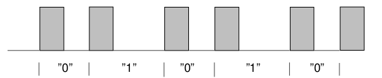
Aermec RC model A01
Hoping that all Aermec remote controls would behave the same, I tested another RC, only to find out that it is completely different: even bit encoding is not the same!
Looking at the mark and space timings, where marks all have the same duration and spaces two possible durations, this is very likely a "pulse distance modulation".
Recent Posts
- harman/kardon HK 620 no speaker output
- Volvo XC60 cannot play (some) MP3 tracks
- Solarmax Inverters Data to MQTT
- Monitor your FRITZ!Box Internet bandwidth usage using lots of free software: Python, Redis, Raspbian, Mosquitto, Node-RED, InfluxDB, Grafana
- IoT garden irrigation for less than 30€
Archive
2021
2020
- October (1)
2019
- April (1)
2018
Categories
- arduino (4)
- IoT (6)
- open hardware (1)
- open source (4)
- networking (2)
- Cisco (1)
- audio (1)
Tags
- openenergymonitor grafana influxdb nodered mqtt mosquitto arduino esp8266 (1)
- grafana influxdb nodered mqtt mosquitto (1)
Authors
- Mauro (10)
Comments
Comment awaiting approval 5 years, 3 months ago
New Comment