Posted by: Mauro 7 years, 1 month ago
A little, self contained demo of what you can do with Arduino.
Objective: challenge your friends response time, by pressing a button as fast as you can when an LED turns off. The time elapsed between the LED turning off and the button press is shown on a 4-digit display, in milliseconds.
Components:
- 1x Arduino Uno
- 1x Push-button switch
- 1x LED
- 1x 74HC595 (8 bit shift register)
- 1x HS410561K-32 (4 digits 7-segments display, common anodes)
- 8x 220 Ω resistors (current limiting the leds of the display)
- 1x 330 Ω resistor (current limiting the stand-alone led)
- 1x 10 kΩ resistor (button pull-down)
The shift register helps driving the 7 segments that compose each digit and the decimal point (totalling 8 leds for each digit), using only three Arduino pins. Eight bits are sent serially to the shift register, and the corresponding logical levels will be output in parallel on eight of its pins.
Since you can light up only one digit at a time, the microcontroller will have to continuously scan the display, activating in turn one of the four common anodes corresponding to the four digits.
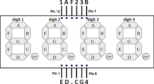
Common anode, 4 digits display
The display has 12 pins: 4 pins correspond to the four digits (for example, the pin marked "1" - i.e. pin 12 - is the common anode of "digit 1"); the 8 remaining pins correspond to the seven segments (A to G) and to the decimal point.
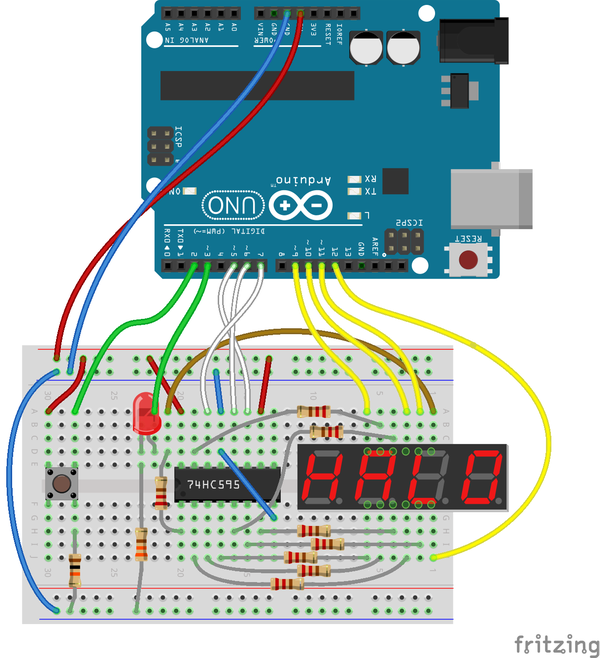
Wiring
Sketch
The loop function is modeled around four states:
0 - idle: while waiting for a "player", the display shows seconds elapsed since power on; pressing the button enters next state
1 - the led is turned on for a random time interval between 4 and 9 seconds, and the display is not updated; the player is ready to catch the led turning off
2 - response time measurement: the display starts counting the milliseconds, until the player presses the button
3 - show result: the display shows the response time in milliseconds; a button press, or 60 seconds of inactivity, returns to the idle state
const int digitPins[4] = {9,10,11,12}; // display 4 common anodes (one pin per digit)
const int clockPin = 5;    // 74HC595 Pin 11 (clock)
const int latchPin = 6;    // 74HC595 Pin 12 (latch)
const int dataPin = 7;     // 74HC595 Pin 14 (serial data in)

const int ledPin = 3;
const int buttonPin = 2;

const byte digit[10] =      // seven segment digits in bits
{
  B00111111, // 0
  B00000110, // 1
  B01011011, // 2
  B01001111, // 3
  B01100110, // 4
  B01101101, // 5
  B01111101, // 6
  B00000111, // 7
  B01111111, // 8
  B01101111  // 9
};

int digitBuffer[4] = {0,0,0,0};
volatile byte btnEvent = 0;
int s = 0; // state 0 = idle, 1 = ready random led time, 2 = measure resp time, 3 = show result
unsigned long tstart, resptime;
unsigned long idlestart = 0;

void setup() {
  for(int i=0;i<4;i++)
  {
    pinMode(digitPins[i],OUTPUT);
  }
  pinMode(latchPin, OUTPUT);
  pinMode(clockPin, OUTPUT);
  pinMode(dataPin, OUTPUT);

  pinMode(ledPin, OUTPUT);
  pinMode(buttonPin, INPUT);

  randomSeed(analogRead(0));
  attachInterrupt(digitalPinToInterrupt(buttonPin), btnPressed, RISING);
}

// writes "value" on the 7-segments display,
// with an optional decimal point at the specified position

void updateDisp(unsigned long value, byte decpos = 0) {

  // load 4 digits in digitBuffer
  digitBuffer[3] = value % 10;      // units
  digitBuffer[2] = (value/10)%10;   // tens
  digitBuffer[1] = (value/100)%10;  // hundreds
  digitBuffer[0] = (value/1000)%10; // thousands

  for (byte scandigit=0; scandigit<4; scandigit++) {

    // set all common anodes (+) to LOW
    for(byte j=0; j<4; j++) digitalWrite(digitPins[j], LOW);
    digitalWrite(latchPin, LOW); // disable shift register output
    // turn off all segments by setting HIGH all cathodes
    shiftOut(dataPin, clockPin, MSBFIRST, B11111111);
    digitalWrite(latchPin, HIGH); // enable shift register output

    delayMicroseconds(100);

    // set common anode of current digit to HIGH
    digitalWrite(digitPins[scandigit], HIGH);

    digitalWrite(latchPin, LOW); // disable shift register output
    if ((decpos > 0) and ((decpos - scandigit) == 1))
      // turn on decimal point near scandigit
      shiftOut(dataPin, clockPin, MSBFIRST, ~(digit[digitBuffer[scandigit]] | B10000000));
    else
      shiftOut(dataPin, clockPin, MSBFIRST, ~digit[digitBuffer[scandigit]]);

    digitalWrite(latchPin, HIGH); // enable shift register output
    delay(1); // wait 1 ms, before turning on next digit
  }
}

void loop() {
  switch (s) {
    case 0: // idle
      digitalWrite(ledPin, LOW);
      updateDisp(millis()/1000, (millis()/1000) % 4 + 1);
      if (btnEvent) {
        btnEvent = 0;
        if (millis() > (idlestart + 1000)) { // debounce
          s = 1;
        }
      }
      break;

    case 1: // led on for random time
      updateDisp(0);
      digitalWrite(ledPin, HIGH);
      delay(4000 + random(5000));
      if (btnEvent) {
        btnEvent = 0;
      }
      digitalWrite(ledPin, LOW);
      tstart = millis();
      s = 2;
      break;

    case 2: // measure response time
      updateDisp(millis() - tstart, 1);
      if (btnEvent) {
        btnEvent = 0;
        resptime = millis() - tstart;
        s = 3;
      }
      break;

    case 3: // show result
      digitalWrite(ledPin, HIGH);
      updateDisp(resptime, 1);
      if (btnEvent) {
        btnEvent = 0;
        if (millis() > (tstart + resptime + 1000)) { // debounce
          idlestart = millis();
          s = 0;
        }
      }
      if (millis() > (tstart + 60000)) { // return to idle after 1 min
        idlestart = millis();
        s = 0;
      }
      break;

    default:
      s = 0;
  }
}

void btnPressed() {
  btnEvent = 1;
}
Share on Twitter
Share on Facebook
Recent Posts
- harman/kardon HK 620 no speaker output
- Volvo XC60 cannot play (some) MP3 tracks
- Solarmax Inverters Data to MQTT
- Monitor your FRITZ!Box Internet bandwidth usage using lots of free software: Python, Redis, Raspbian, Mosquitto, Node-RED, InfluxDB, Grafana
- IoT garden irrigation for less than 30€
Archive
2021
2020
- October (1)
2019
- April (1)
2018
Categories
- arduino (4)
- IoT (6)
- open hardware (1)
- open source (4)
- networking (2)
- Cisco (1)
- audio (1)
Tags
- openenergymonitor grafana influxdb nodered mqtt mosquitto arduino esp8266 (1)
- grafana influxdb nodered mqtt mosquitto (1)
Authors
- Mauro (10)
Comments
There are currently no comments
New Comment